3 Phase Monitoring Relay Wiring Diagram

How To Connect A Three Phase Monitor Relay Macromatic Industrial Controls In 2020 Relay Monitor Connection

Contactor Wiring Guide For 3 Phase Motor With Circuit Breaker Overload Relay Nc No Switches Electrical Online 4u Reverse Basic Electrical Wiring Motor

Pin By Emmanuel Granados Reyes On Electrical Wire Size Table Wire The Smaller The Gauge Number The Larger The Conductor Size In 2020 Relay Monitor Connection

Ad Ebay 5x Grv8 04 M460 3 Phase Voltage Monitoring Relay Phase Sequence Phase Failu X6o1 In 2020 Led Indicator Relay Power Rating

35 Inspirational Winch Relay Wiring Diagram In 2020 Warn Winch Relay Diagram

Minilec 3 Phase Monitoring Relay Vcf D2 Din Rail Mounted Electrikals Com Relays 4wireunderandovervoltagerelaydinrailmount Relay Online Marketing Mounting

It may be installed in a motor feeder and control the supply to a number of motors or in a motor branch circuit to protect a single motor and its load.
3 phase monitoring relay wiring diagram. Connect the three phase line line voltage to terminals 1 2 and 3 see wiring diagram on the side of the relay or figure 2 on reverse side. 1 phase 2 phase 4 wire 3 phase line. The device operates according to the closed circuit principle g incorrect phase sequence or phase failure. Different regions may use different voltages.
As standard the d65vmls series relays are in the. How to connect a three phase monitor relay macromatic industrial within 3 phase motor wiring diagram contactor relay by admin through the thousand images online regarding 3 phase motor wiring diagram contactor relay choices the very best selections together with greatest resolution exclusively for you all and now this photographs is actually one among images series in our greatest graphics. Do not connect output wires to terminals 7 12 until later step 12. A connection to the neutral or ground is not required in wye systems.
The cm pfs is used to monitor three phase mains for incorrect phase sequence and phase failure. Operating mode the three phase main to be monitored is connected to terminals l1 l2 l3 in accordance to the wiring diagram. Overload relay 1ct m m motor 3ct to 120 v separate control ot is a. Although these systems may seem intimidating at first a walkthrough on 3 phase wiring for dummies will help clarify the whole situation.
When the fault goes away the phase monitor relay will reclose its n o. Phase voltage monitoring relay used for phase loss phase sequence voltage unbalance overvoltage and undervoltage monitoring with 3 phase power supplied by 208 480v ac 50 60hz also with timer counter function 0 1 30s adjustable delay time compact size relay with 1 co 1 nc contacts real time lcd display for voltage fault and operation state din rail mounting. Note due to wrong connection done the above diagram is update in the above diagram i shown the complete method of wiring or connection of phase failure relay diagram with circuit breaker cont actor overload relay push button switches and electric motor however lets talk about this step by step. Contact but the motor starter or contactor will not energize until either a start pushbutton is closed or a two wire control unit i e limit switch proximity switch relay contact etc is closed.
Wiring diagram book a1 15 b1 b2 16 18 b3 a2 b1 b3 15 supply voltage 16 18 l m h 2 levels b2 l1 f u 1 460 v f u 2 l2 l3 gnd h1 h3 h2 h4 f u 3 x1a f u 4 f u 5 x2a r power on optional x1 x2115 v 230 v h1 h3 h2 h4 optional connection. They can also be found in large residential complexes and appliances requiring a large amount of power. Like subscribe and don t skip the.

Dpa51am44n 3 Phase Monitoring Relay Relay Engineering

3 Phase Dol Starter Connection Three Phase Induction Motor Dol Starter In 2020 Motor Electrical Circuit Diagram Delta Connection

Unique Winch Contactor Wiring Diagram Diagram Diagramtemplate Diagramsample Lighting Diagram Installing Recessed Lighting Power Led

5 Pin Momentary Switch Wiring Diagram Switch Diagram 3 Way Switch Wiring

New Wiring Diagram Hager Contactor Warn Winch Relay Diagram

How To Read Electrical Relay Diagram Standard Symbols Used For At Within Panel Wiring Generator Transfer Switch Electrical Diagram Electrical Wiring Diagram

A Complete Guide About How To Wire A Room Or Room Wiring Diagram For Single Room In House Relay Switches Circuit

Image Result For 8 Pin Relay Pinout

Tvr2000 1 Phase Failure Relay Relay Failure Electricity

Magnetic Contactor Schematic Diagram Electrical Circuit Diagram Hvac Air Conditioning Basic Electrical Wiring

Star Delta Starter Electrical Circuit Diagram Basic Electrical Wiring Home Electrical Wiring
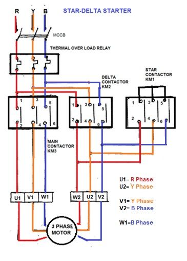
Star Delta Starter Electrical Circuit Diagram Basic Electrical Wiring Home Electrical Wiring

New Mercedes Glow Plug Relay Wiring Diagram Electrical Wiring Diagram Diagram Motorcycle Wiring

Circuit Diagram Of Relay Driver Used For Controlling Home Appliances Home Automation System Home Automation Electronics Basics

Wiring Riddle No 3 Auto Transfer Switching Diagram Transfer Switch Electrical Circuit Diagram Generator Transfer Switch

Contactor Wiring Diagram With Timer New Mars Time Delay Relay Wiring Diagram Wiring Library Timer Relay Diagram

12v 40a Led Fog Light Wiring Harness Laser Rocker Switch Relay Picturesque Led Diagram Light Switch Wiring Electrical Wiring Diagram Electrical Circuit Diagram

12v 5 Pin Relay Wiring Diagram Deltagenerali Me Light Switch Wiring Electrical Wiring Diagram Electrical Circuit Diagram
1

14 Automatic Wiring Diagram For Ceiling Fan Ceiling Fan Switch Ceiling Fan Wiring Ceiling Fan Pull Chain

Pin On Wiring Diagrams

Wiring Diagram For 3 Phase Ac Motor Diagram Diagramtemplate Diagramsample Baldor Pioneer Stereo

Phase Failure Relay Entes Electronic Istanbul City Turkey In 2020 Relay Failure Istanbul City

Tyco 5 Blade Relay Wiring Diagram Wiring Diagram Electronic Circuit Projects Relay Electromagnet
Dpa02cm40 Carlo Gavazzi Monitoring Relay 3 Phase 380 415vac 8a Spdt

House Wiring Diagram Home Electrical Wiring Residential Electrical Electrical Wiring

How To Wire Relays Light Flash Two Wire German Vehicles Negative Output From Alarm Keyless Entry Dual Make Spst Relay Negativity Relay Diagram

14 Pin Relay Connection Diagram Finder 14 Pin Relay Wiring Diagram Diagram Relay Electrical Diagram

A Plc Has Been Programming To Control The Starting And Stopping Of A Three Phase Electric Motor The Program Plc Programming Ladder Logic Electronic Schematics
Jungheinrich Fork Truck Type Dfg Tfg 316 320 420 425 430 540 545 550 Workshop Service Manual Circuit Diagram Circuit Diagram

Voltage Monitoring Relays Buy Minilec 3 Phase Voltage Monitoring Relay Scanners Online Electrikals Com Buyminilecrelaysonlin Relay Scanners Stuff To Buy

Relay Testing Services Vadodara India Relay Analysis System

Bmw E36 Auxiliary Fan Wiring Diagram Natebird For E36 Wiring Diagram Bmw E30 Bmw Diagram

Awesome Isuzu Alternator Wiring Diagram Diagrams Digramssample Diagramimages Wiringdiagramsample Wiringdiagram

Ah3 3 On Delay Timer Timer Electrical Installation Electrical Diagram

Plumbing Diagrams For Rv Sink Click Here For A Block Diagram Showing Allenhancements And Their Rv Water Rv Repair Plumbing

On Off Three Phase Motor Connection Power Control Electrical Circuit Diagram Basic Electrical Wiring Electrical Wiring Diagram

Honeywell S8610u Wiring Diagram 3 Diagram Honeywell Honeywell Thermostats

Wiring Diagram Of Washing Machine Motor Http Bookingritzcarlton Info Wiring Diagram Of Wa Washing Machine Motor Washing Machine Basic Electrical Wiring

Pin On Wiring

Fan Regulator Connection Diagram And Internal Circuit Explanation Electrical Circuit Diagram Electrical Diagram Electrical Wiring Diagram

12v Relay Wiring Diagram 5 Pin Bokeh Aplikasi

A Motor Controller Schematic Motor

