3 Wire Rtd Bridge Circuit

Rtd Wheatstone Bridge Circuits Wheatstone Bridge Circuit Bridge

Rtd Sensor Connections Sensor Connection Pie Chart

Measuring Strain With Strain Gages National Instruments
Rtd Wheatstone Bridge Circuits Instrumentation Tools

How Does 3 Wire Rtd Or Resistance Measurement Works In Bridge Of Wheatstone Electrical Engineering Stack Exchange
Chapter 7 Temperature Measurement Rtd Measurement Circuits Engineering360
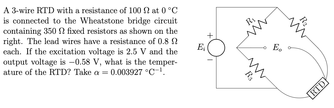
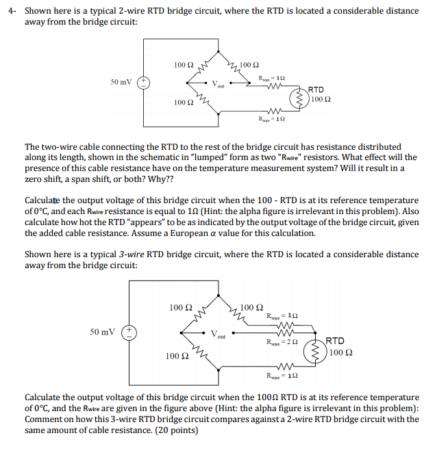
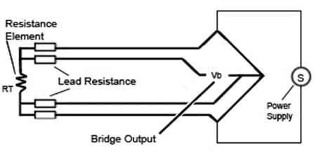
Figure 3 shows a typical 3 wire constant current circuit while figure 4 shows a constant voltage excitation circuit.
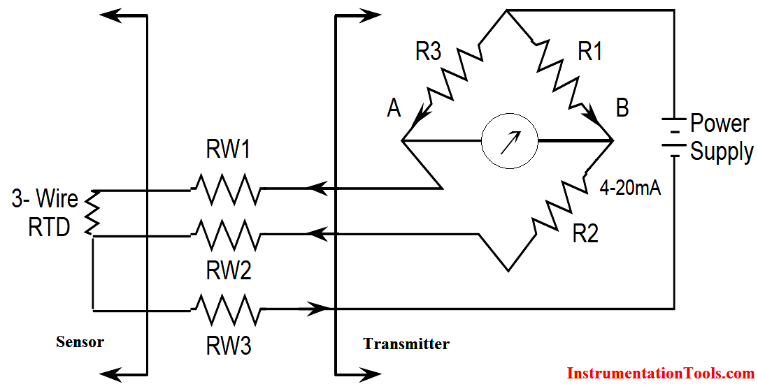
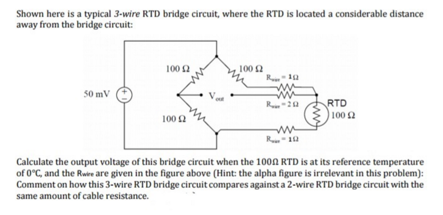
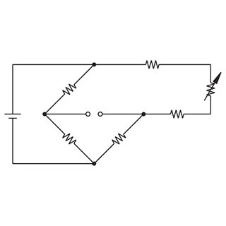
3 wire rtd bridge circuit. The design uses a resistance temperature detector rtd in a 3 wire configuration to minimize the errors introduced by the lead resistances of a remotely located rtd. It consists of running an additional wire to one contact of the rtd. Since l1 and l3 are in separate arms of the bridge resistance is canceled. A 2 wire rtd configuration is the most useful with high resistance sensors or in applications where a great deal of accuracy is not required.
Incidentally the same limitation as for three wire connections applies if the fixed bridge direct reading approach is being used see section 3 3. Tempco matches rtd leads within 5. No current flows through it while the bridge is in balance. The third wire r l3 in figure 3 is a voltage sensing wire only it is not in series with any of the bridge arms therefore it has no effect on bridge balance or temperature stability.
The 3 wire circuit makes it possible to compensate for the line resistance both in its amount and also in its temperature variation. It can be seen that the resistance of the right leg of the wheatstone bridge is r1 r2 rw2. The power supply is connected to one end of the rtd and the top of the wheatstone bridge. This circuit assumes high impedance at eo and close matching of resistance between wires l2 and l3.
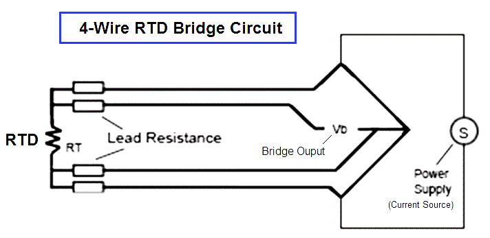
While the three wire circuit offers several advantages over the two wire circuit in some special applications involving. A 24 bit delta sigma δσ analog to digital converter adc is used in this design which features two integrated precision current sources that excite the 3 wire rtd. This results in two measuring circuits of which one is used as reference. As a rule of thumb 3 wire circuits can handle wire runs up to 100 feet.
The resistance of the left leg of the bridge is r3 rw3 rtd. Similar to the two wire circuit the current source ik2 is used to measure the temperature dependent resistance rt including the lead and terminal contact resistances. Differential temperature rtd s to measure differential temperatures using bridge circuitry a second rtd is simply introduced into the bridge circuit alongside the first sensor. 3 wire rtd circuit in a three wire circuit two constant current sources are used in order to compensate for the disadvantages described above for the two wire circuits.

Lecture 9 Resistance Temperature Detector Youtube Lecture Kharagpur Temperatures

Lab Iv Opamp Signal Conditioning Circuit For 3 Wire Rtd Bridge Chin Tamapipon 58010294

How To Identify The Transistor Terminals Transistors Identify Led
Solved Shown Here Is A Typical 3 Wire Rtd Bridge Circuit Chegg Com

Resistance Temperature Detector Rtd Questions 1 This Or That Questions Detector Temperatures

Labiv Op Amp Signal Conditioning Circuit For 3 Wire Rtd Bridge Kmitl58010911
Rtd Wiring Diagrams


Lab Iv Opamp Signal Conditioning Circuit For 3 Wire Rtd Bridge Markawan Maneesinthop

Lab Iv Opamp Signal Conditioning Circuit For 3 Wire Rtd Bridge Nattarin Saibua 58010665

Lab Iv Opamp Signal Conditioning Circuit For 3 Wire Rtd Bridge Chantharat Phakdeewong

What Is An Rtd Rtd Types Uses And More By Jms Southeast

What Is Rtd Sensitivity Resistance Thermometer Sensitive Tools

Solved A 3 Wire Rtd With A Resistance Of 100 S2 At 0 C I Chegg Com

Process Pressure Measurement Objective Questions This Or That Questions Pressure Measurements
Why We Use Wheatstone Bridge In Rtd Instrumentationtools

Ramps 1 4 Wiring Google Search Electronics Projects Ramp Wire
Https Encrypted Tbn0 Gstatic Com Images Q Tbn 3aand9gcsx5msxuruep93sxwa72s3gz4j9e0 P3yc6gjbmy2ukzxyddfwh Usqp Cau

3 Wire Rtd Sensor Wiring A 3 Wire Rtd 3 Wire Rtd Probe
How 3 Wire Rtd Lead Wire Resistance Eliminated

Quartz Crystal Microbalance The First Scientific Qcm Entirely Open Source Arduino Sensor Analog To Digital Converter

Pin On Raspberry Pi

Pic Icd2 Pickit 2 Pickit 3 Adaptateur De Programmation Pickit2 Pickit3 Programmeur Universel Seat Pics

Pin On The Ocean Reef And Beneath
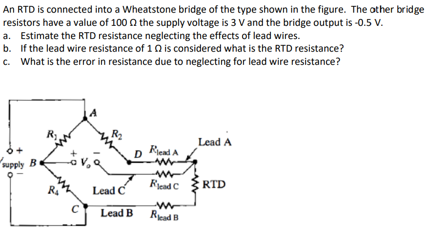
Solved An Rtd Is Connected Into A Wheatstone Bridge Of Th Chegg Com

Permanent Magnet Moving Coil Instruments Pmmc Permanent Magnet Magnets Coil

Difference Between 2 Wire Rtd 3 Wire Rtd And 4 Wire Rtd S

Process Technology Operator Academy Inst Tech Rtd Must Knows

Pin On Smart Home Automation
Https Coloradomtn Instructure Com Courses 1060747 Files 48211126 Download Wrap 1

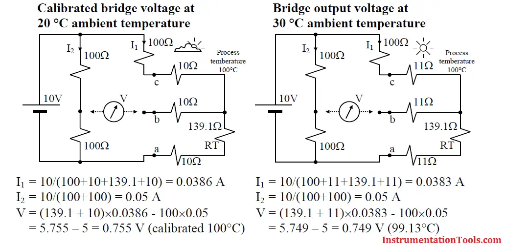
Ambient Temperature Effects On Rtd Instrumentation Tools
Rtd Elements And Sensors Introduction And Tables
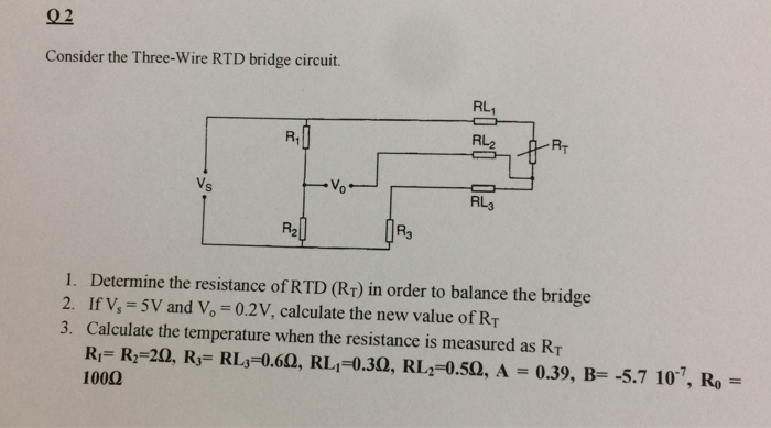
Solved Consider The Three Wire Rtd Bridge Circuit Determ Chegg Com
Temperature Sensor Basics Ni
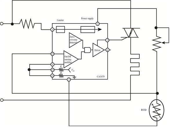
Solved Show How To Connect The Ca3079 Zero Voltage Switch To A Chegg Com

Hipotronics 800pl 880 Pl Dc Hipot Insulation Tester 80kv 5ma Tester Measuring Instrument Ebay

Pin On Hydroponic Gardening


Resistance Thermometer Wikipedia
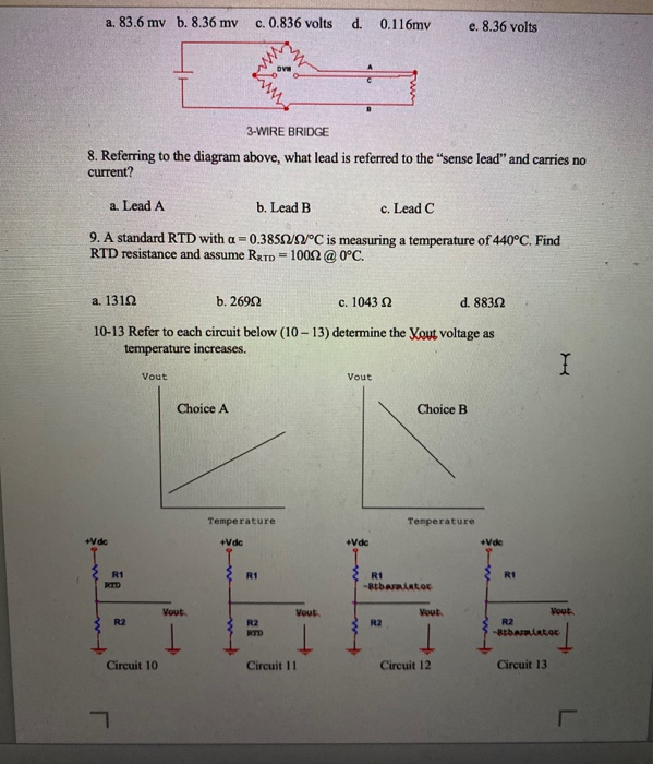
Solved Highlight The Correct Answer See Example 1 Below Chegg Com

Pin On Tools